

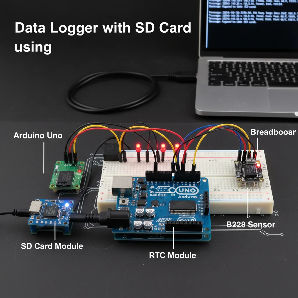
Data Logger with SD Card Using Arduino
Design a data logging system using Arduino and SD card to store real-time sensor data for analysis, monitoring, and long-term record keeping.
Inclusive of all taxes
- Secure payments via Razorpay
- 7-day returns on defective items
- GST invoice on every order
Free delivery on orders above ₹2,000
Delivers in 4-7 business days
Check delivery at your pincode
₹8890.00
Inclusive of all taxes

Components
9 items

Difficulty
Advanced
Build Time
4 – 6 hours
Project Details
How It Works
 How It Works
The project works by using an Arduino microcontroller to collect data from connected sensors (like temperature, humidity, light, or voltage sensors). The Arduino uses SPI communication protocol to interface with an SD card module, which manages the SD card storage. The Arduino code initializes the SD card, creates or opens a file (typically in CSV format), writes sensor readings to the file at regular intervals, and closes the file. The data is stored in a non-volatile format on the SD card, allowing it to persist even when power is removed. The stored data can later be transferred to a computer via an SD card reader for analysis using tools like Excel or Python.
Prerequisites
Basic knowledge of Arduino programming, understanding of digital and analog sensors, familiarity with SPI communication protocol, and experience with file handling concepts. Users should also know how to install Arduino libraries and have the Arduino IDE installed on their computer.
What You'll Learn
 What You'll Learn
Understanding and implementing SPI for SD card communication
Learning to create, write, and manage files on SD cards
Implementing real-time data acquisition and storage
Working with FAT32 file system on embedded devices
Reading and processing data from various sensors
Understanding permanent storage for analysis and monitoring
Key Features
Continuously logs sensor data as it's collected
Data persists even after power loss
Can log data from temperature, humidity, light, voltage sensors
Optional real-time clock for accurate time tracking
Used in environmental monitoring, industrial systems, research
Foundation for IoT edge devices and data acquisition systems
What's Included in the Kit
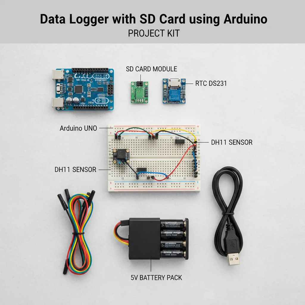
| Component | Qty | Price |
|---|---|---|
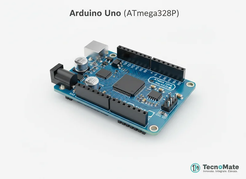 | 1 | ₹767.00 |
 | 1 | ₹589.00 |
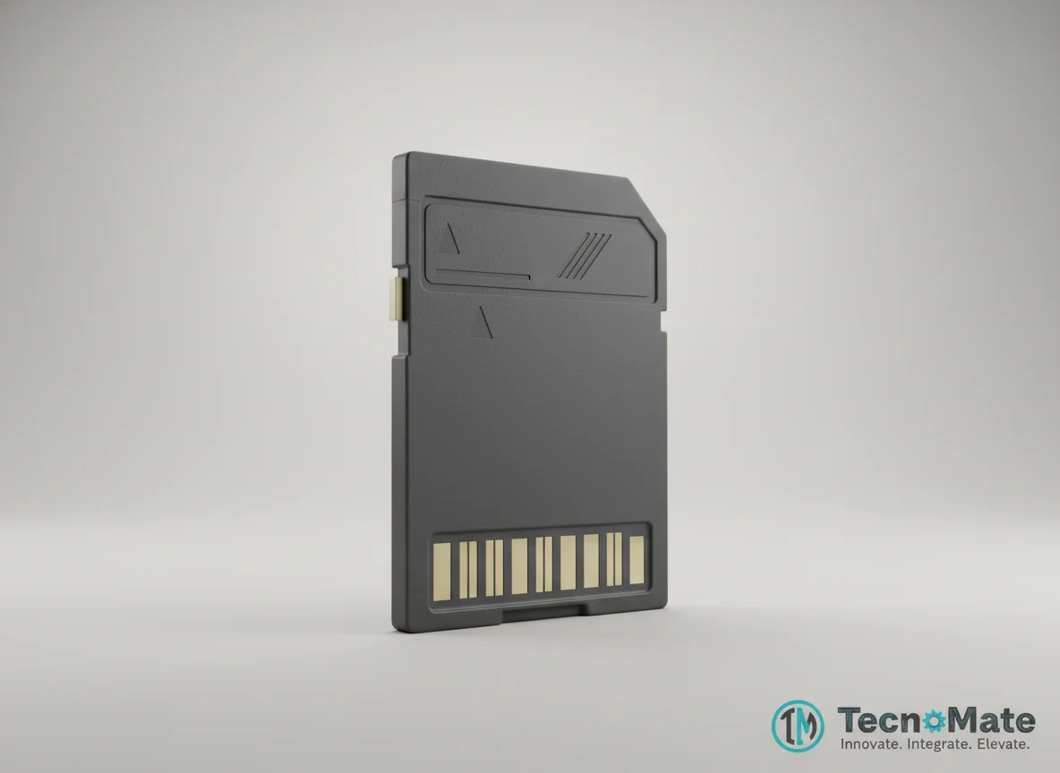 | 1 | ₹589.00 |
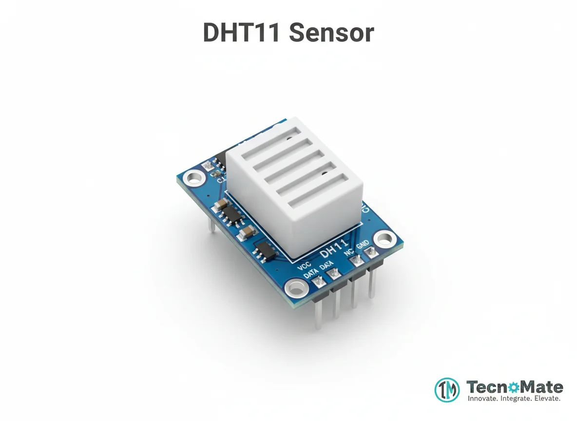 | 1 | ₹59.00 |
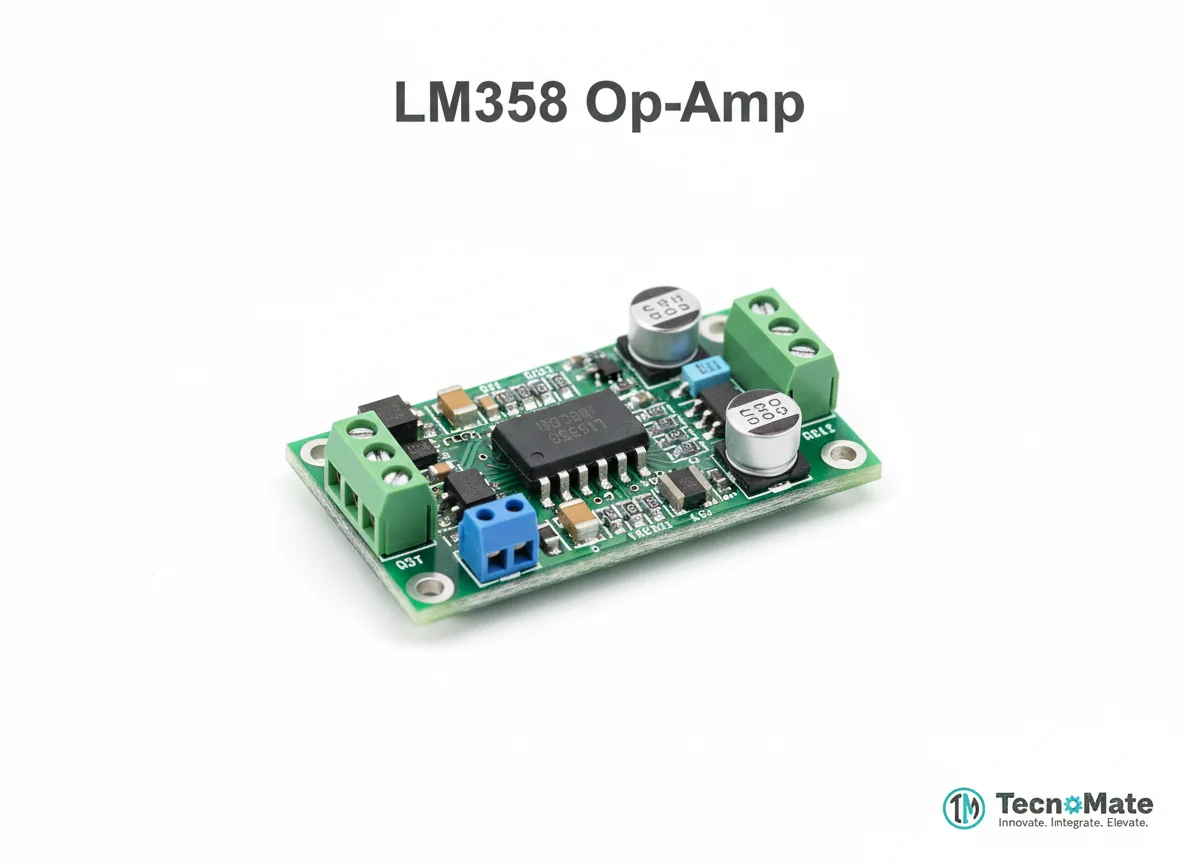 | 1 | ₹289.00 |
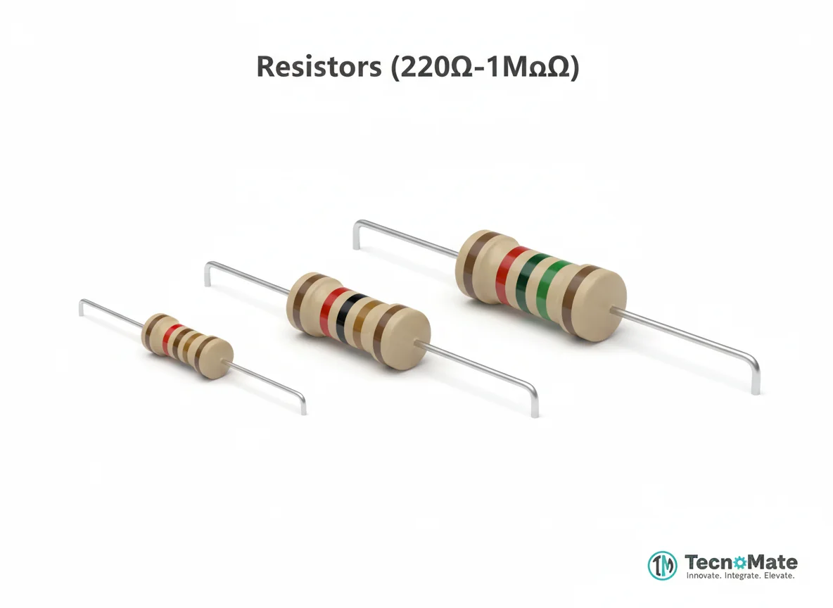 | 1 | ₹260.00 |
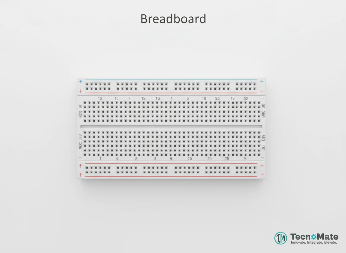 | 1 | ₹77.00 |
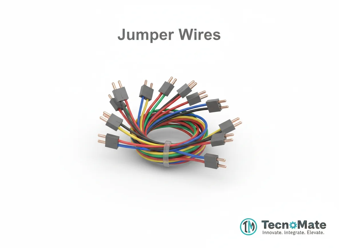 | 1 | ₹171.00 |
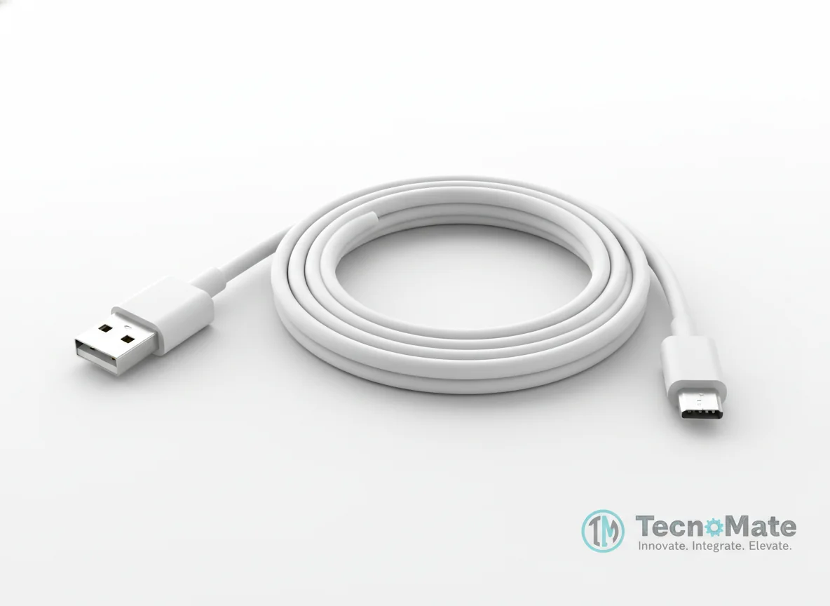 | 1 | ₹190.00 |
Operating Instructions
Pin Connections
 Pin Connections
| MCU Pin | Connected To | Purpose | Notes |
|---|---|---|---|
| D10 | SD Card Module CS | Chip Select for SPI communication | SPI Chip Select pin |
| D11 | SD Card Module MOSI | Master Out Slave In for SPI data | SPI MOSI pin |
| D12 | SD Card Module MISO | Master In Slave Out for SPI data | SPI MISO pin |
| D13 | SD Card Module SCK | Serial Clock for SPI timing | SPI SCK pin |
| 5V | SD Card Module VCC | Power supply for SD module | Ensure 3.3V modules use level shifting |
| GND | SD Card Module GND | Ground connection | Common ground |
| A0 | Sensor Output | Analog input for sensor data | Example for analog sensor |
| 5V | Sensor VCC | Power supply for sensor | Check sensor voltage requirements |
| GND | Sensor GND | Ground connection for sensor | Common ground |
Tools Required
 Tools Required
Safety Precautions
Handling
- ⚠Do not remove SD card while writing
- ⚠Safely eject SD card from PC before removal
Electrical
- ⚠Use proper voltage levels (3.3V modules need level shifting)
- ⚠Power OFF before rewiring connections
Operating
- ⚠Avoid loose connections that could cause short circuits
- ⚠Ensure proper grounding to prevent data corruption
Frequently Asked Questions
 Frequently Asked Questions
Q:What file format should I use?
Q:Can I log multiple sensors?
Q:Do I need an RTC module?
Q:Can I use Arduino Nano?
Product images are for illustration purposes only. Actual products may differ in appearance, packaging, or specifications. See our Terms of Service.